The recently formed IEEE P802.3cn project will define two groupings of Ethernet optical PHYs. The first grouping will target 50, 200 and 400 Gigabit Ethernet operation for reaches up to 40 km over single-mode fiber (SMF). The second grouping of optical PHYs will be new to the Ethernet family as it extends Ethernet’s reach to 80 km over DWDM systems for 100 and 400 Gigabit Ethernet operation. The needs of cable service providers (which I’ll refer to here as multiple service operators, or MSOs) was a primary justification for this exciting new family of PHYs, in particular at 100 Gbps for deployments first and at 400 Gbps long term. In this article, the need for this new family of Ethernet optical PHYs is discussed.
Figure 1. Remote PHY overview.
Remote PHY creates new requirements
MSOs are going through a transition today that is as transformational as adding fiber was decades ago. Up to now, DOCSIS and video packet cores, and their PHY (RF signal execution), have been delivered in one box or at least one location. This approach created a plant distribution environment that needed linear optics, modulating RF signals directly. Moving forward, however, the PHY is moving away from the signal processing cores as Remote PHY devices (RPDs) are placed in the field at the end of fiber runs, in cable nodes, close to the home where coaxial distribution begins (see Figure 1). This move in turn creates a new digital Ethernet network between the PHYs and packet cores, now referred to as the converged interconnect network (CIN). As an aside, this evolution also enables cores from dedicated boxes to evolve into cloud compute applications, which adds to the extent of this transition.
Ethernet has been front and center to Remote PHY (R-PHY) from the beginning; by definition, DOCSIS and video payloads are organized in pseudo wires encapsulated within IP and Ethernet headers as shown in Figure 2. The use of Ethernet and IP encapsulation ensures that R-PHY is fully usable with common networking elements such as switches and routers, giving full access to their broad variety and flexibility.
Figure 2. Ethernet and IP encapsulation of R-PHY payload.
It’s not all copy and paste, however. What also makes R-PHY interesting, even within the already vast world of networking, is that it puts Ethernet in a large access deployment with particular requirements. One example is the requirement of distance, where client-to-client optical connections (Ethernet native connections) can span from 5 to 80 km and sometimes more. To date Ethernet connectivity has been defined for up to 40 km. Longer distances, usually in the hundreds or thousands of kilometers, are facilitated by the addition of an extra photonics framing layer, Optical Transport Network (OTN).
Another example is the use of dense wavelength-division multiplexed (DWDM) Ethernet signals. Although there is nothing technical that prevents DWDM transmissions beyond 40 km, as is done at 10 Gbps, a well-defined formal Ethernet definition at 100 Gbps is important for the cable MSO market to leverage large volumes and accompanying lower cost. In particular for the cable market, as shown in Figure 3, this Ethernet application needs to meet particular architecture qualities at 100 Gbps.
This was the motivation for a call for interest to expand the scope of the IEEE “Beyond 10 km Optical PHY Study Group,” where contributors made a case for a robust client optical specification that would enable the lowest cost and lowest power 100 Gbps for the Ethernet access in cable networks. IEEE is now taking up this effort via the newly minted P802.3cn task force. As a jump start, CableLabs has also released a definition for an interoperable 100-Gbps coherent physical interface (https://www.cablelabs.com/point-to-point-coherent-optics-specifications/).
Application
R-PHY technology solved one of the principal challenges with legacy RF distribution out of the headend or hub, namely, the difficulty in increasing RF port density as expansion of DOCSIS service groups demands more endpoints. Effectively, there is only so much faceplate space to populate with more and more RF connections. But while the scale of RF connectivity has been eased by putting RPDs in the field, the challenge of scale remains for optoelectronics and fiber.
By default, the headend and hubs currently support the scale of legacy deployments of optical gear and fiber already in the plant. Ultimately it would be ideal if, even while experiencing rapid growth, the CIN enables the same scale of optics at the hub and fiber in the plant as exists now. The transition to R-PHY would then pose no deployment challenges for other new or existing revenue-generating services that might use other fibers or wavelengths and need their own connectivity space in headends or hubs, such as mobile backhaul or direct virtual private network (VPN) connections. This ability to scale with current hub or headend resources is the intent for those of us who seek to optimize connectivity for R-PHY.
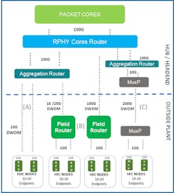
In Figure 3, we expand on the architecture progression that includes networking equipment and the optics that support it. There are many ways to build out the CIN, but we generalize it to three basic options. The three options have in common a collection of packet cores and a layer of 100-Gbps routing to coalesce signaling from the cores. Then the options become unique.
Figure 3. Remote PHY architecture options.
The first option (A) we call direct connect, where every RPD has one corresponding 10-Gbps port at the aggregation router in the headend or hub. This approach leverages the use of symmetric DWDM ZR (80 km), industrial temperature transceivers. In this option, if the transition to R-PHY includes a growth of 12 nodes per parent node (we’ve seen over 20), then the fiber distribution now needs to accommodate 12 more lambdas and 12 more optical transmitters and receivers. If the legacy system already leveraged analog DWDM in signal distribution to parent nodes, then this multiplicative effect of lambdas could pose a problem to the use of single-fiber solutions.
The great upside to option (A) is that all the gear needed to deploy it already exists. (Note the inclusion of an optical DWDM multiplexer and demultiplexer is implicit for all options but not shown in the picture.)
Option (B) eases the fiber scaling challenge of direct connectivity by taking the aggregation function deeper into the network via the inclusion of a field aggregation router (FAR). Ideally the FAR goes into the fiber plant as far as the parent node that spawned a collection of RPDs. But it also can be at a more central location such as a distribution cabinet or even small hub. In any case, the principle of aggregating as far as possible remains. Option (B) ultimately leverages a single large throughput uplink signal, such as 100 Gbps, and since the original network was already DWDM and up to 80 km, the 100-Gbps signaling must keep those qualities. This 100-Gbps signal can connect directly to the 100-Gbps routers, which removes an entire layer of routing from the headends or hubs where sensitivity for thermal and physical footprint is always at a premium.
But between option (A) and option (B) 100 Gbps the inclusion of a field router can have a transitional step. This “mid-step” allows lower throughput uplink signals from some of the available 10-Gbps ports existing from option (A). This is possible due to the initial and well-defined growth of RPD signals, which eventually nears 10 Gbps but is much less than that in the early years of deployment.
There is also a third option (C), which includes the insertion of a time-domain multiplexing technique for optical signals. This effectively introduces an OTN photonic layer to the CIN. This technique could be useful in certain cases, but because it cannot leverage any concurrency of payloads, its uplink capacity scales linearly as the number of endpoints times the port speed. It therefore is certainly not ideal for R-PHY distribution, which can leverage replicated signals by the typical nature of DOCSIS payloads.
In approach (B), the FAR can ingress replicated data only once and distribute correctly to recipient endpoints. This is done by effectively leveraging multicast functions that enable a non-blocking environment at lower bandwidths. On the other hand, the technology of option (C) is useful for dedicated full-bandwidth signals, such as inter-hub connections. Note that in option (C), in any case where between 10 and 20 RPD endpoints are being aggregated, a 200-Gbps uplink must be used, due to the nature of OTN framing and optics options. This could leave a lot of paid capacity unused.
One of the main questions for the inclusion of the FAR, then, is how much uplink bandwidth is actually required? For the answer we lean on networking capacity calculations that relate to growth at the subscriber level. The general rule is that after the PHY (wherever it may be), bandwidth scales to what is provisioned by DOCSIS; before the PHY, bandwidth scales in terms of usage. In our case, the CIN is before the PHY, so the uplink capacity scales based on subscriber usage.
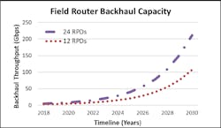
Figure 4 shows an example of the backhaul capacity needed for a FAR servicing 12 or 24 RPDs, where each RPD has 50 households passed with 75% penetration. In this case each subscriber starts with a 3-Mbps usage and grows at 40% compounded annual growth rate (CAGR). Notice that over time the router uplink capacity grows, making strides beyond 10 Gbps in the first part of the decade; as bandwidth continues to grow, it surpasses 50 Gbps and is well on the way to 100 Gbps by the end of the decade.
Figure 4. Uplink capacity over time for field aggregation router (FAR).
Ideally, the uplink capacity can be addressed with one wavelength, directly from the headend or hub to the FAR. If the cost is right, this is fertile ground for an operationally efficient early introduction of coherent 100-Gbps 80-km DWDM technology, which can take on the qualities needed for wavelength specificity and distance from day one.
Bringing it home
As the cable industry moves towards 100-Gbps use, there is a parallel dynamic in the broader Ethernet optics market. In both, a path is needed for what comes after the 10-Gbps ZR DWDM transceivers used for mobile, data center and enterprise point-to-point applications. This is a very large application space, and it is precisely why the work at IEEE P802.3cn is critically important to cable operators.
We propose principally that if the cable MSO space aligns itself with the dynamics of the broader Ethernet market, then the introduction of 100-Gbps 80-km DWDM optics in cable access can benefit from large volumes and commodity pricing. Such a circumstance would of course be quite beneficial to the long-term robustness of the CIN and R-PHY in general.
Ethernet Alliance member Fernando Villarruel is an architect for the office of the CTO at Cisco’s cable access unit, where he has responsibility for the long-term vision of access networking, which includes all Layer 1-3 activities. Fernando has delivered practical solutions to the MSO space for more than 17 years, first making fundamental contributions to linear access networks, and now leading the transition to the Ethernet/IP deployments needed to build out Remote PHY.


